PRODUCTS AND SERVICES
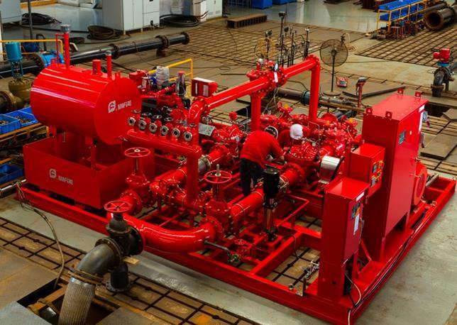
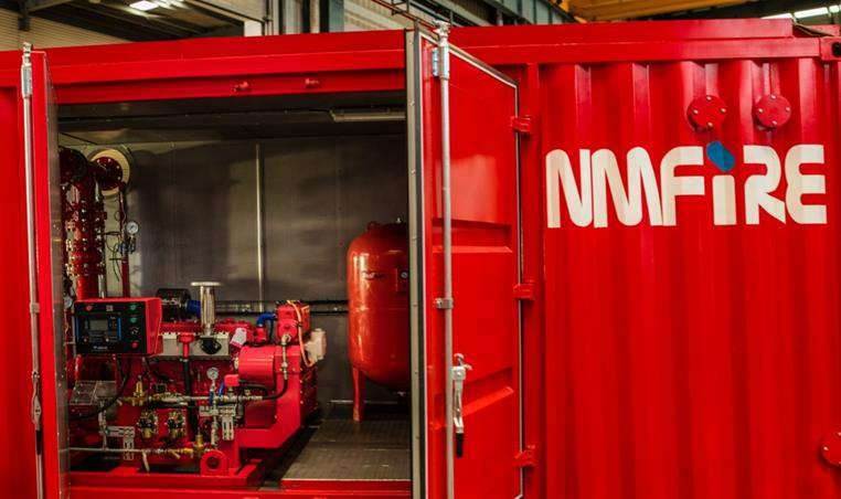
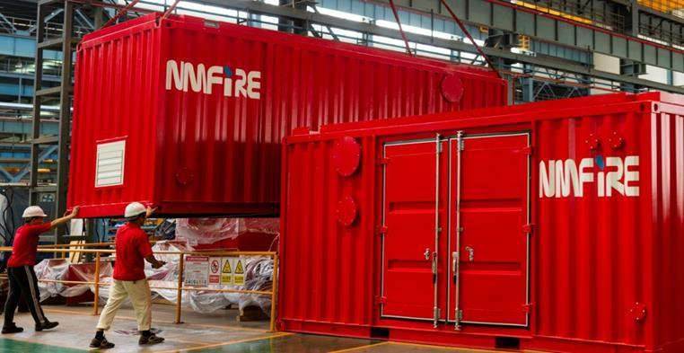
NETIC can provide Engineering, Design, Supply, Installation, Testing, Commissioning, and Fire Fighting Training services for industries such as power plants, substations, telecommunication centers, and railways.


NETIC can provide Engineering, Design, Supply, Installation, Testing, Commissioning, and Fire Fighting Training services for industries such as power plants, substations, telecommunication centers, and railways.


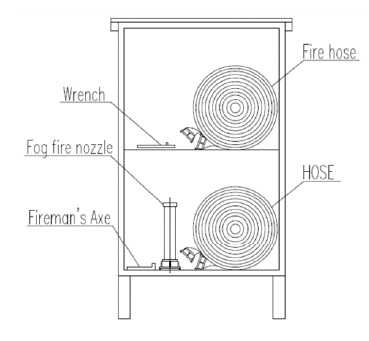
Equipment lists:
1 unit – 40 mm Ø adjustable water
combination nozzle, pistol grip type
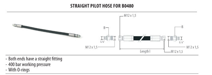
2 units – 40 mm Ø Fire Hose with connector, double
jacketed, 15 meters long
1 unit – Straight Pipe Wrench, 71.1 mm jaw capacity
1 unit – Fireman’s Axe
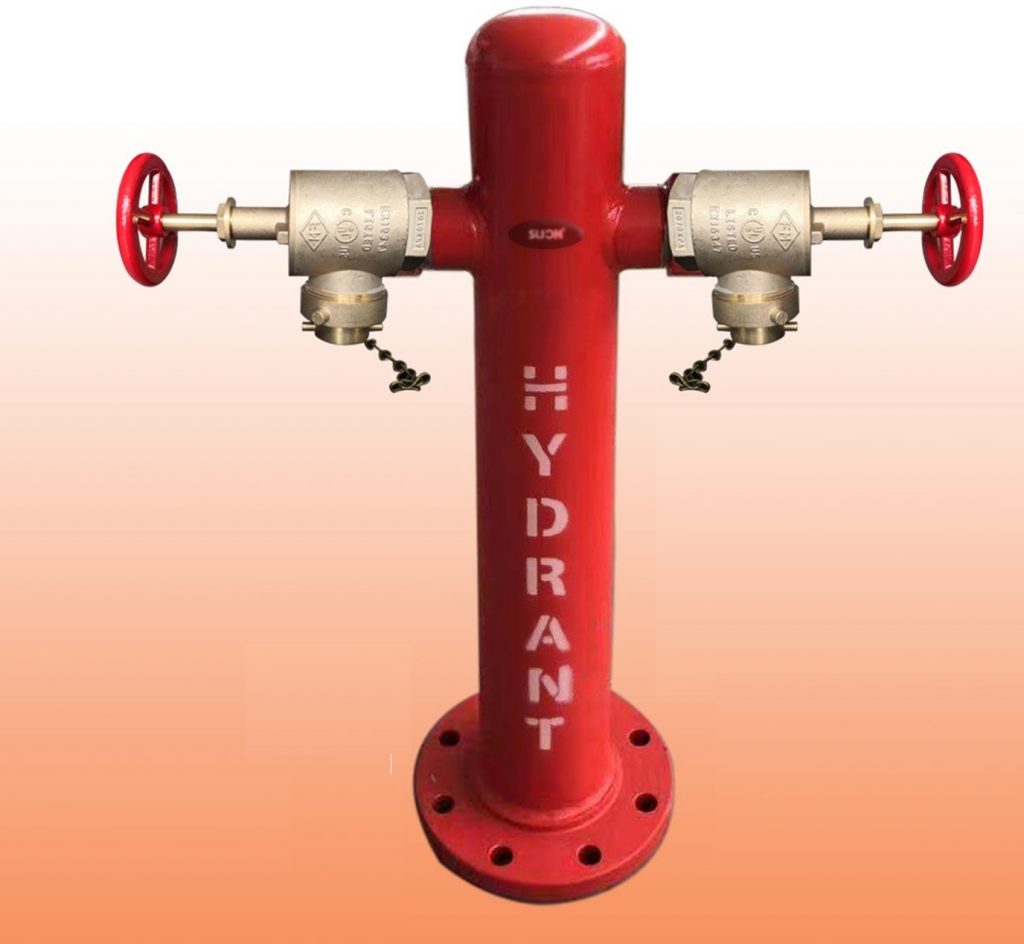
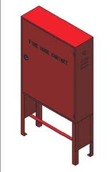
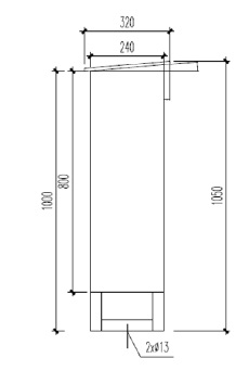
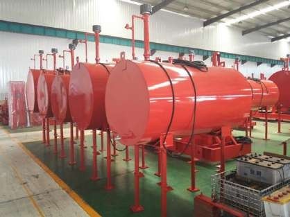
Note:1)Hydrant box color: Red 3000L
2)Hydrant box material: C.S
3)Hydrant box thickness: 1.0mm
For ordinary outdoor service, woven single jacket, lined fire hose is recommended. If yard surfaces are rough and will cause heavy
wear, or if water pressures are over 150 psi (1035 kPa), double jacket hose is advised. Hose that may come in contact with acid, acid
fumes or other corrosive materials should be covered. If the hose must be stored in a damp location, it should be treated for protection
against mildew unless the jacket is woven entirely of synthetic fibers.
For indoor service, lightweight single jacket, lined hose or linen hose is most often used. The lining of the lightweight hose is thin
enough so that the hose can be mounted on the semiautomatic pin type hose racks and laid out without jamming. The conventional
fire hose for outdoor use cannot be mounted on these racks due to its heavier lining. This hose will jam the racks.
Lightweight, double jacket, thin-lined fire hose is designed for use on rough surfaces where weight is a prime consideration, such as
forestry use or use in backpacks in high rise buildings. It may also have some use as a rack hose in manufacturing areas such as
foundries, steel mills, etc. This type of fire hose is not a substitute for conventional double jacket hose where service demands are
high and weight is of secondary importance.
Some listings specify a service test pressure. Service test pressure is that pressure to which a hose should be periodically subjected
to determine its suitability for continued service. The service test pressure is at least 10% greater than the normal operating pressure.
Alternatively, some hoses listed state “Tested To XXX.” This refers to the manufacturer’s proof pressure, which is two times the
service test pressure. If no test
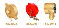
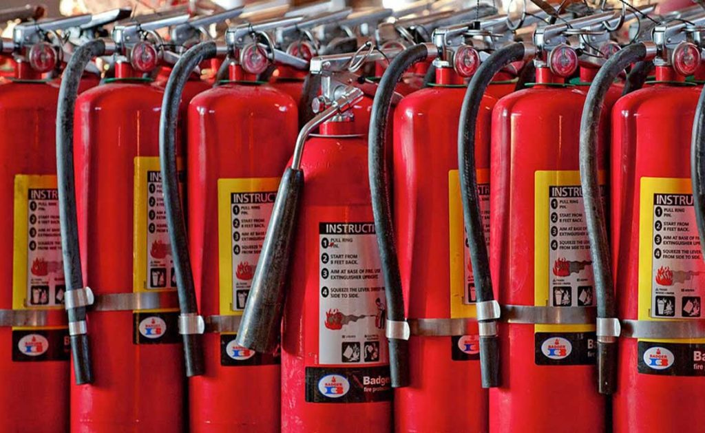
40 mm Ø Fire Hose with connector, double
jacketed, 15 meters long40 mm Ø Fire Hose with connector, double
jacketed, 15 meters long
Listed or Approval: UL/FM
Couplings Brass NST/NPSH expansion ring threaded coupling
Tset Pressure: 150 psi
Brust pressure 450 psi
Original: CHINA
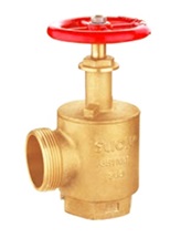
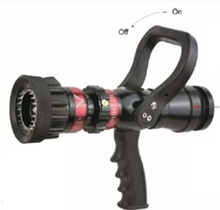
40 mm Ø adjustable water combination
nozzle, pistol grip type
1. Strong Light Weight Aluminum Construction.
2. Constant Selectable Flow rate.
3. Tight Stream and 130°Wide Dense Fog Pattern.
4. Quality Stream Performance Even At Low Pressure
5. Replaceable Spinning Teeth.
6.Excellent for Use with Foam Tube.
7. Working Pressure:100PSI or 7Bar.
8. Connections Size Available:1.5″ 2.5″
9.Connections Type Available:Storz, NH,BIC or JIC
10.MAX Flow Distance:34M.
11.MAX Working Pressure:16Bar.
Straight Pipe Wrench, 71.1 mm jaw
capacity & Fireman’s Axe
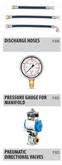
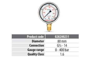
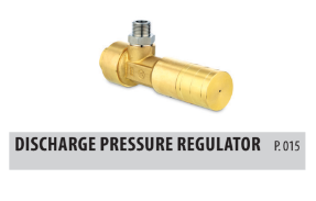
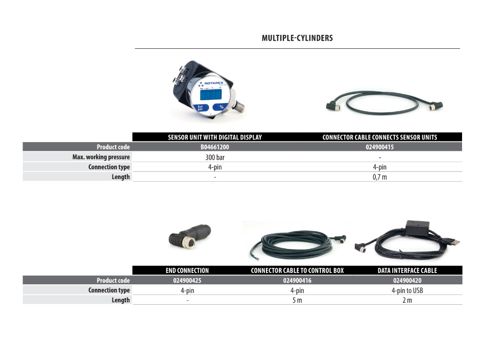
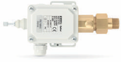
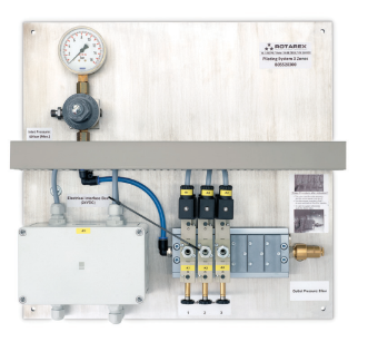
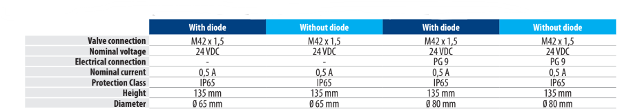
Optional pressure gauge to monitor discharge pressure. Mandatory when using directional valves – multiple zone protection. With glycerine filling.
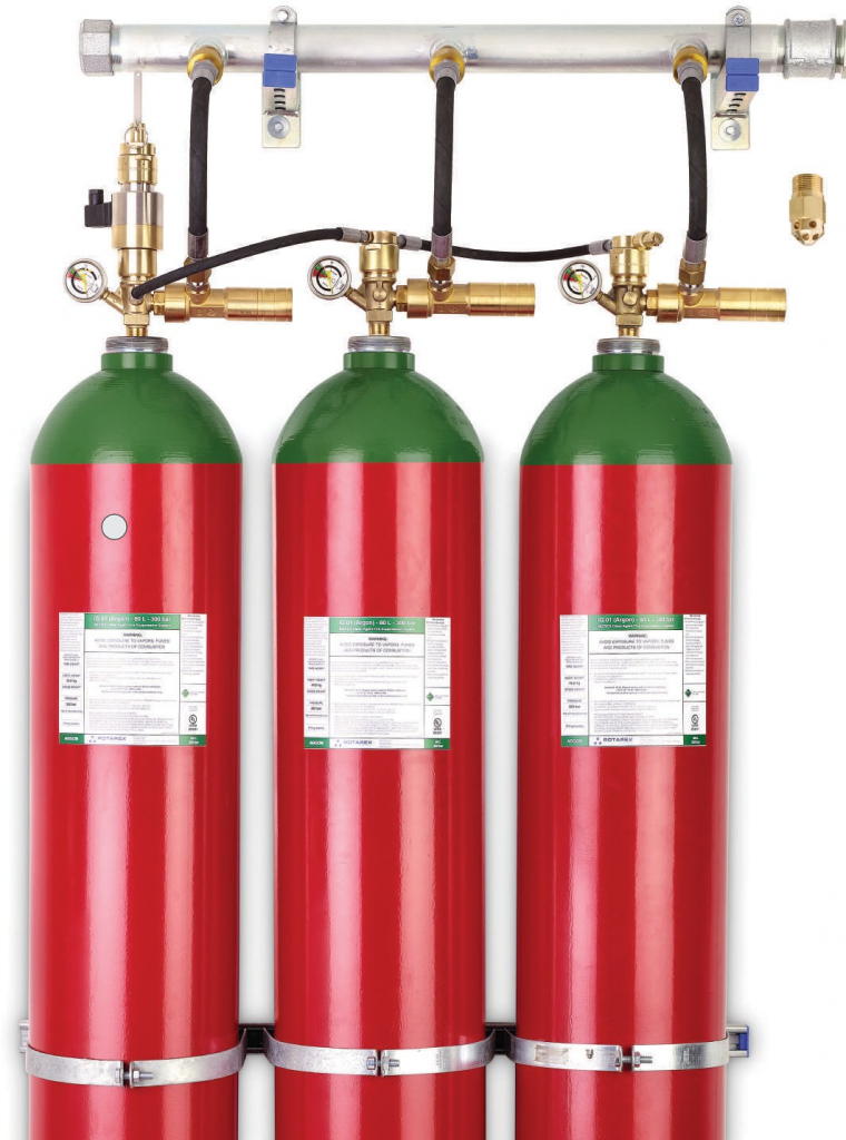
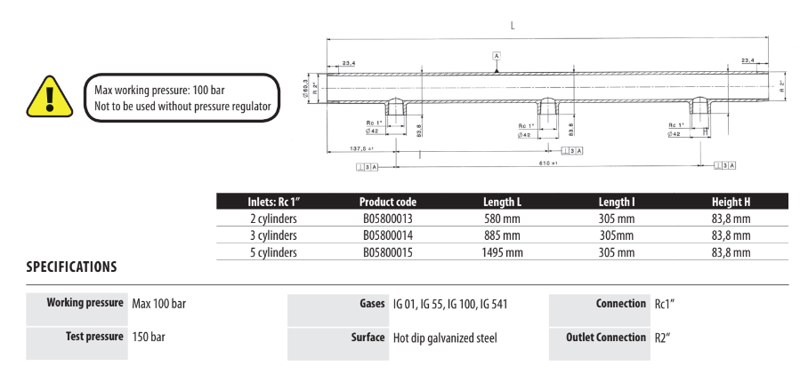
Rotarex Pressure Regulators modulate the discharge pressure to a constant 40-60 bar which still delivers the design concentration within 60 seconds, but with significant performance and cost benefits:
BETTER SAFETY: – Prevents explosive force of discharge
SAVES TIME AND MONEY: – Enables low pressure manifolds & pipework to be used that are lower
cost and easy to install – Reduces the difficulty and cost of locating/fitting pressure vents in the protected space
EASY MAINTENANCE: – After a system discharge, simply remove the regulator, recharge, and
reconnect. No reconditioning necessary – Functional tests are possible even while the system is armed
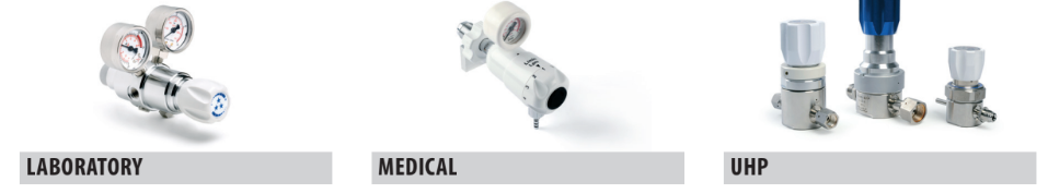
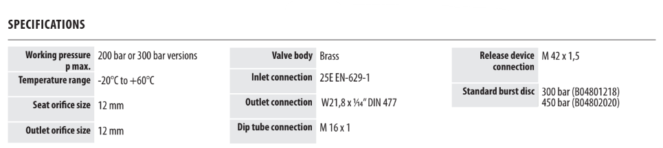
Rotarex adapts its pressure regulation technology from its proven 200 bar/300 bar laboratory, medical and ultra high purity applications to deliver innovative technology for inert gas fire extinguishing systems. The result: confident performance when it really counts.
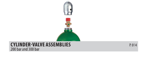
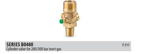
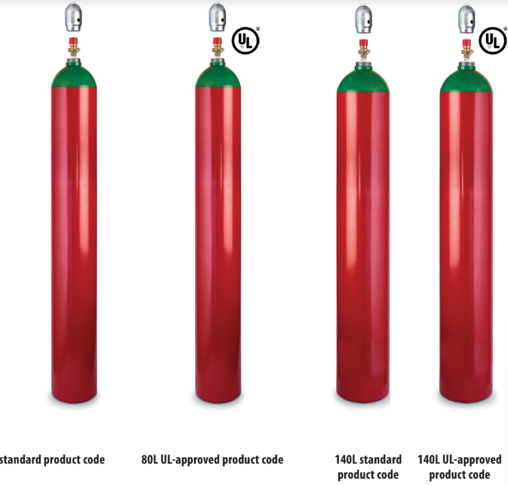
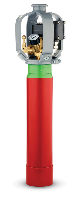
A complete cylinder/valve assembly.
– 80L cylinder for 200 or 300 bar inert gases
– B0480 cylinder valve
– Steel protection cap
– Filled or empty
KEY FEATURES
– Improves productivity: cylinder/valves arrive pre-assembled
– Compliant with CE norms
– Cylinders can be delivered filled or unfilled
– Cylinders color-coded with green band
– UL-approved value burst discs have a higher flow according to CGA S1.1
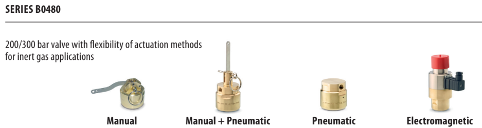
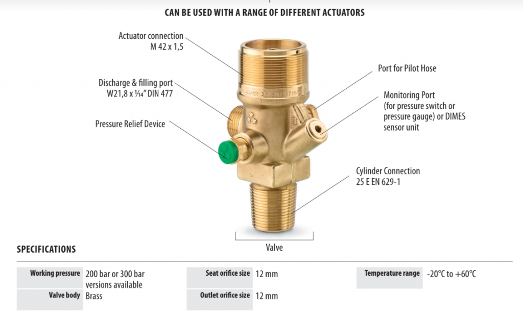
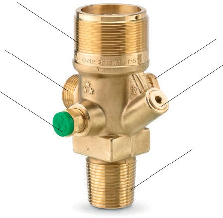
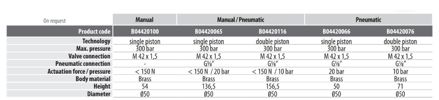
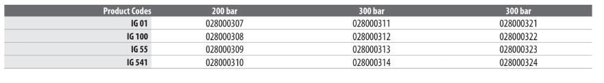
VALVES FOR 200/300 BAR INERT GAS
KEY FEATURES
– Available in 200 bar and 300 bar versions
– Requires one of 4 actuator device options
– UL-approved value burst discs complies with CGA S1.1
– ATEX-approved versions available on demand
ATEX versions not for use with electromagnetic actuators
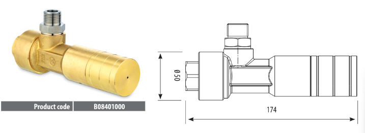
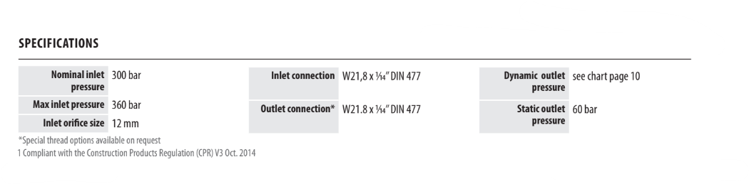
Pressure Regulator to create a constant flow during discharge.
KEY FEATURES
– Reduces discharge pressure to a pre-set pressure (60 bar)
– Attaches to the valve discharge port
– Helps prevent blockage due to line freezing
– Helps reduce pressure blow-outs and venting requirements
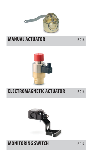
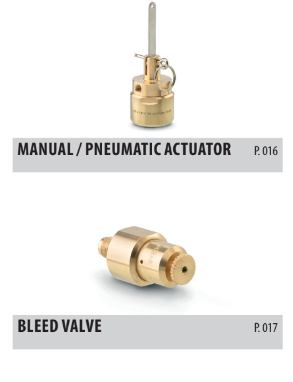
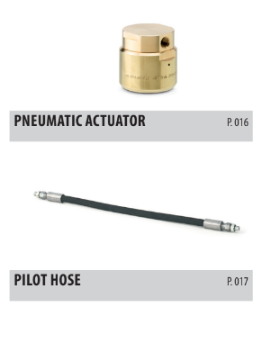
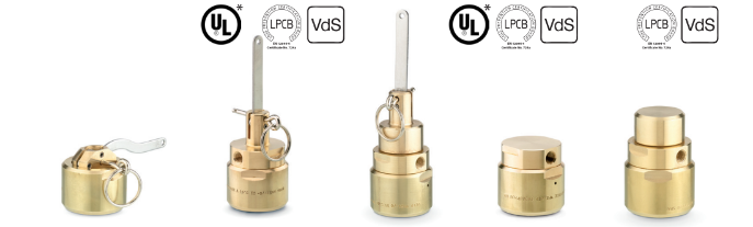
Devices to actuate the release of extinguishing agent For use with SeriesB0481, B0482 and B0480 Valves
Device to electrically actuate the release of extinguishing agent. For use with Series B0481,B0482 and B0480 Valves.
– Most commonly used as a master valve to actuate the system electronically, such as with connection to a smoke or heat detection device
– Electronically actuates the release of extinguishing agent
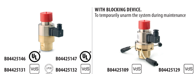
Used to reset the electromagnetic actuator piston when putting the system back in active service after system discharge.
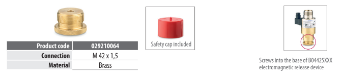
To vent overpressure and prevent false system discharge in the event of a small pressure leak from the cylinders into the pneumatic actuators.
Hose to connect multiple cylinders in a series. Connects a master valve or a pneumatic actuator with an other pneumatic actuator.
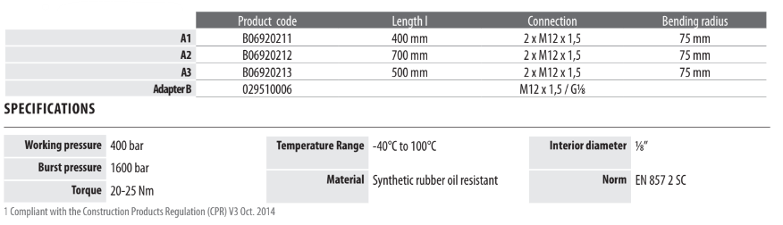
Monitors that the actuator is properly in place to actuate the system
Connects to the alarm box Mandatory according to NFPA 2001 Standard on Clean Agent Extinguishing systems – 2015 edition – (applicable for inert gas system )
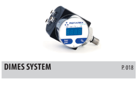
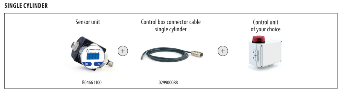
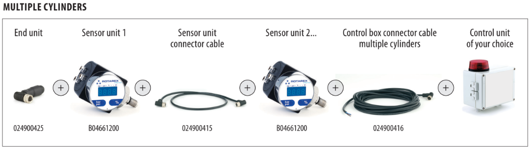
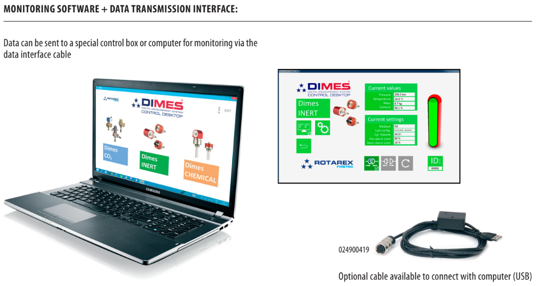
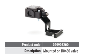
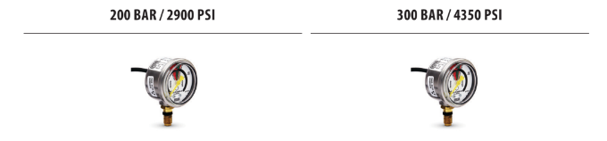
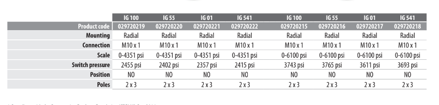
Digital Measurement System for Inert Gas Suppression Systems
KEY FEATURES
– Integrated pressure switch
– Available in 200 or 300 bar versions.
Measures and displays the cylinder pressure for confirmation that the system is properly charged and ready. Integrated pressure switch
KEY FEATURES
– Integrated pressure switch
– Available in 200 or 300 bar versions.
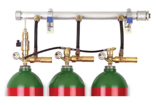
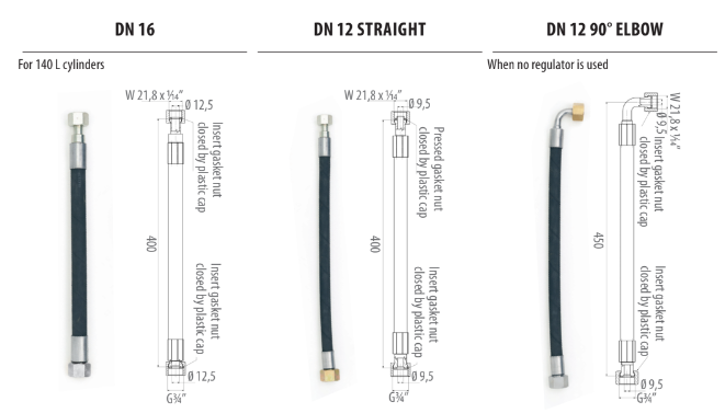
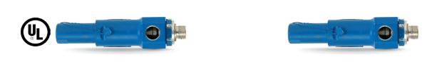
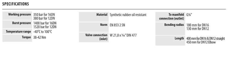
Hose to connect the cylinder valve to the manifold in fixed fire suppression systems.
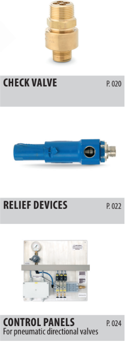
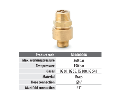
Prevents backflow into the cylinder. Required for each hose attachment to the discharge manifold.
KEY FEATURES
– Integrated pressure switch
– Available in 200 or 300 bar versions.
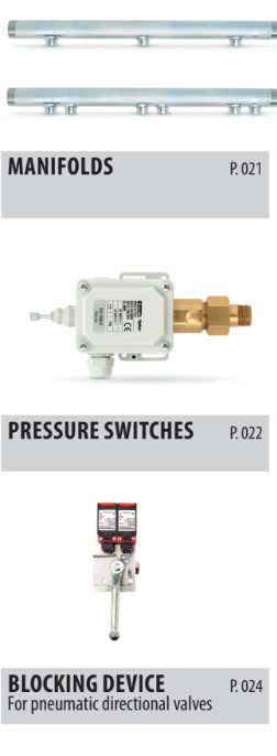
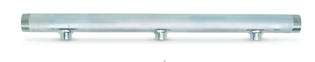
Manifolds to connect from 2 to 5 cylinders (80L cylinders only). Single row configuration.
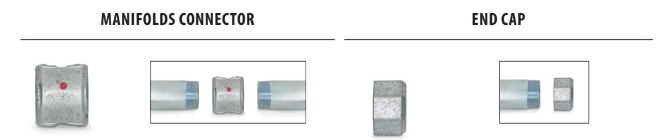
– Fittings to connect or seal Firetec manifolds.
– Respects standards ISO 49 and EN 10242.
– Red dot confirms testing up to 300 bar.
KEY FEATURES
– Integrated pressure switch
– Available in 200 or 300 bar versions.
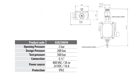
Used to send a signal when the system is discharging. Pressure Activated.
KEY FEATURES
– Sends a signal to a control panel or alarm box at the earliest phase of discharge
– Actuated at 2 bar pressure
– Flexible Voltage/Amp power source
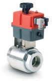
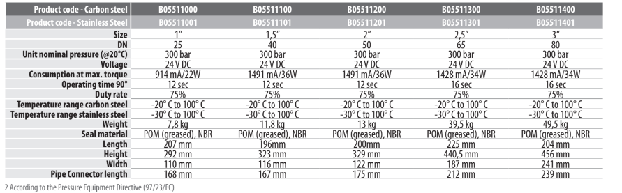
Valve and actuator assembly to isolate separate protection zones from the same cylinder rack. Includes valve + bracket + motor Permits discharge only in the zone with the fire.
KEY FEATURES
– Available in Carbon Steel or Stainless Steel versions
– Choice of 5 diameters: 1”/1,5”/2”/2,5”/3”
– 2-way ball valve
– User-defined installation position and flow-direction
– Output of 2 limit switches
– Electronic over-torque protection
– LED status indication
– Plugs with ISO440 and C192
– IP 65
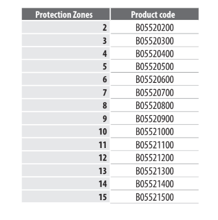
Wall‐mounted switching panel to control directional valve position. Sends a signal to open the directional valve in the zone with a fire
KEY FEATURES
– Available in multiple versions from 2 to 15 zone protection
– For UL, tamper evident seal 028000358 must be used to seal the electrical control box after installation (to be ordered separately)
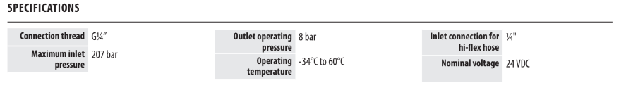
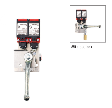
To avoid unintentional operation of directional valves during maintenance. Mandatory for VdS installations
KEY FEATURES
– Easily installs between control panel and directional valve
– Can be locked with a padlock to prevent unintentional
– Two easy‐to‐read switch positions (open or closed)
– One for each directionnal valve
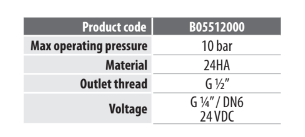
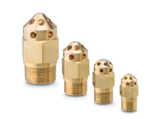
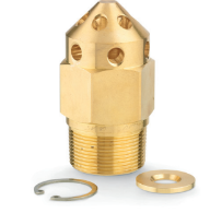
Pre-bored and fully assembled discharge nozzles for CO2 systems For faster and easier installation
Pre-bored and fully assembled discharge nozzles for CO2 systems For faster and easier installation
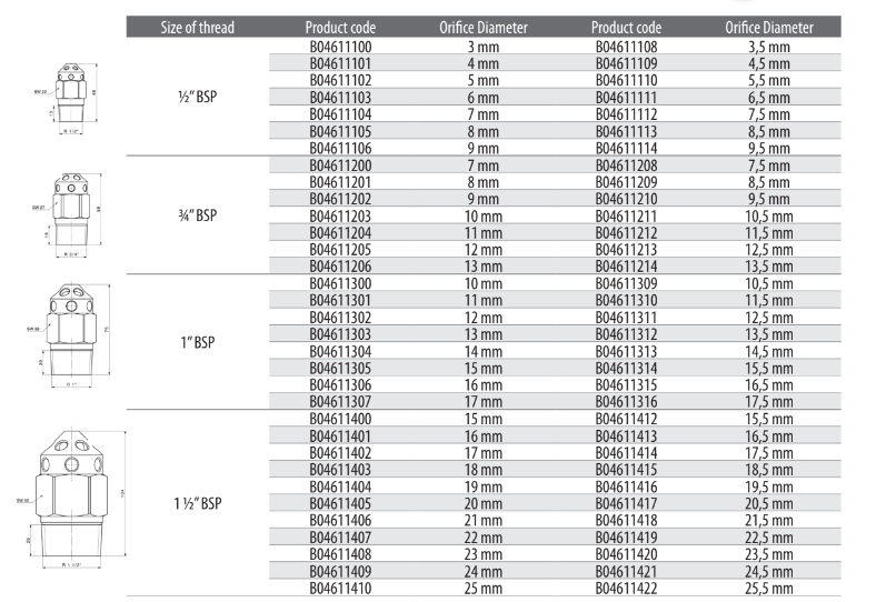
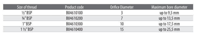
Discharge nozzles where you drill the orifice to your required orifice diameter and assemble yourself. Easier to stock. A more economical alternative.
KEY FEATURES
– Max. working pressure 300 bar
– Material: brass
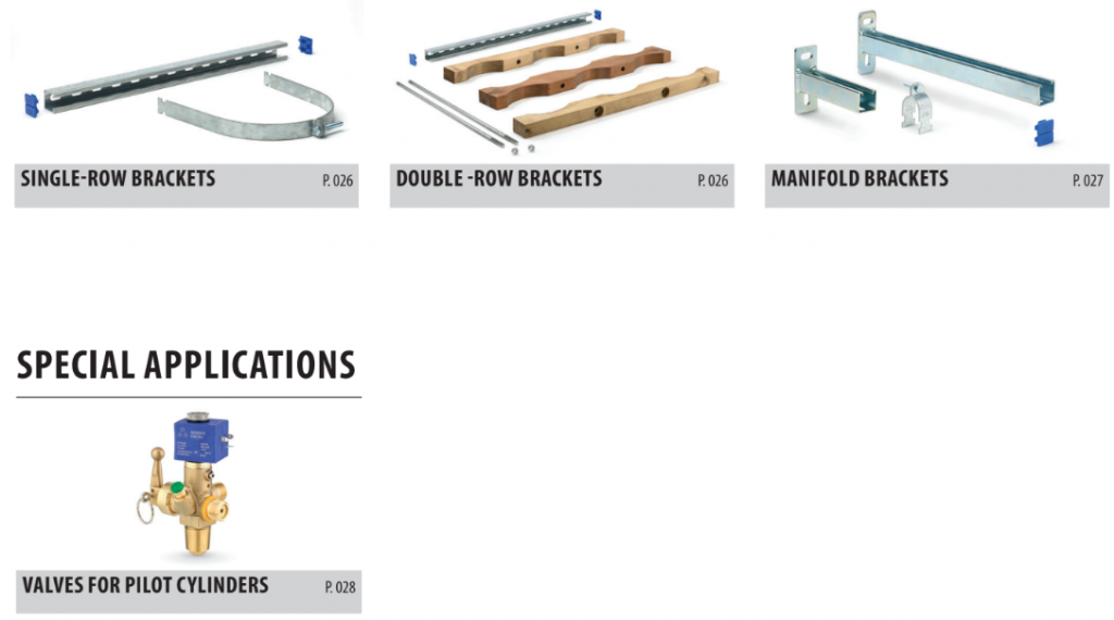
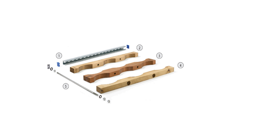
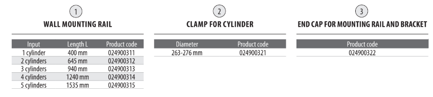
Wall mounting rail, cylinder clamps and end caps parts to mount 80L cylinders to the wall.
KEY FEATURES
– Galvanized steel components for solid support and a long service lifetime
– Wall mounting rail available in multiple lengths to accommodate between 1 – 5 cylinders
– Multiple brackets may be used for more than 5 cylinders
Brackets to secure a double-row of 80L cylinders
KEY FEATURES
– Available in two sizes for 2 or 3 cylinders
– Bracket length: 645 mm for 2 cylinders or 940 mm for 3 cylinders
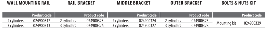
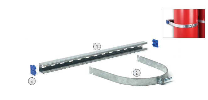
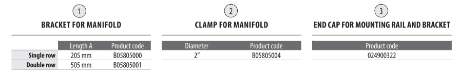
<p>System of brackets, clamps and end caps to mount manifolds to the wall.</p>
KEY FEATURES
– Galvanized steel components for solid support and a long service lifetime
– Wall mounting rail available in 305 mm for single row cylinder configurations, or 610 mm for double-row configurations.
– Manifold clamps available in 2” diameters.
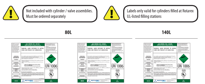
UL-approved cylinder labels for 80L cylinders A mandatory part of a complete UL-approved system. Different labels for each cylinder size,pressure and gas type
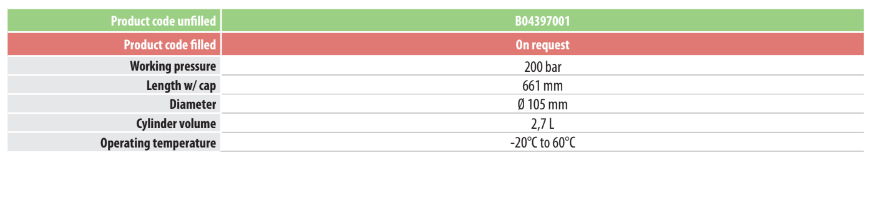
A complete cylinder/valve assembly. Includes:
– π – marked steel cylinder
– B0439 cylinder valve (ATEX)
– Metallic protection cap
Often used as a pilot cylinder for liquid based systems or for smaller installations using a single cylinder.
KEY FEATURES
– Improves productivity: cylinder/valves arrive pre-assembled and ready-to-fill
– Compliant with TPED directive
– Cylinders are standardly delivered unfilled. Filled on request.
– Color coded with green band
– Valve specification on p.29
– ATEX – approved valve
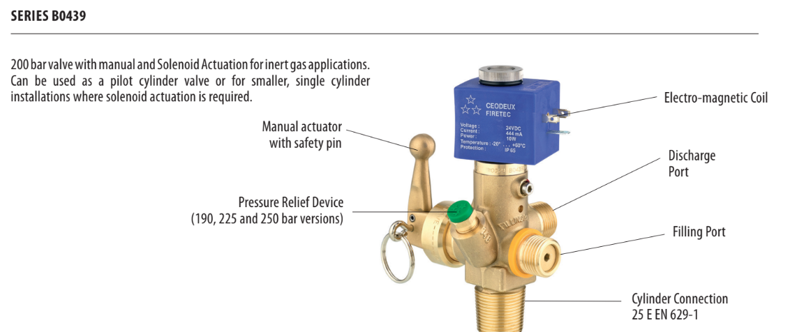
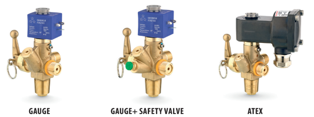
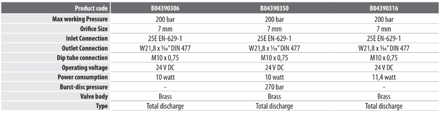
Solenoid-actuated cylinder valve for 200-bar Inert Gas installations.
Often used as a pilot cylinder for liquid based systems or for smaller installations using a single cylinder.
– Available in standard or ATEX versions
– Port configuration for gauge only or gauge+safety valve
– Cylinder / valve assemblies also available
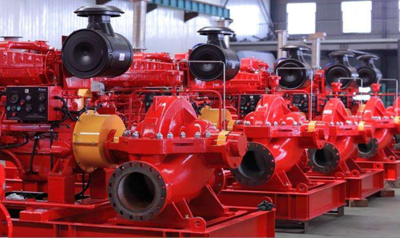
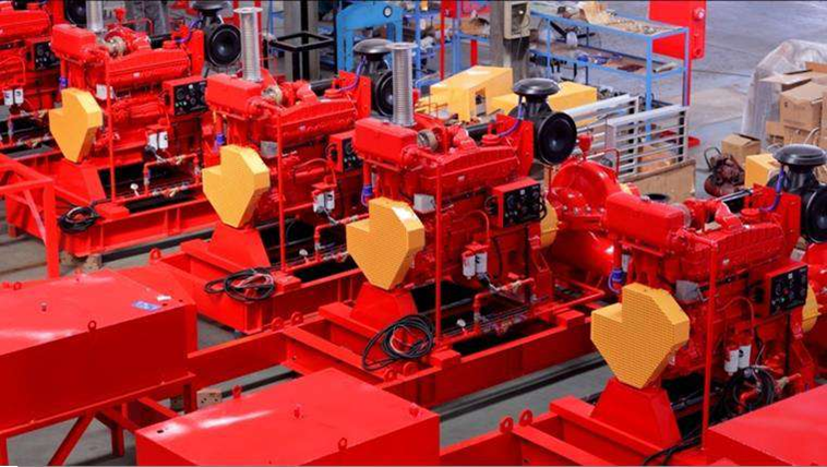
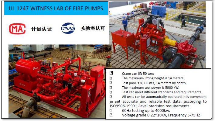
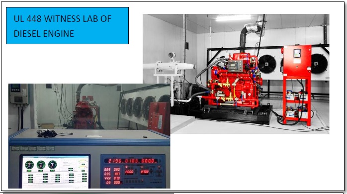
Crane can lift 50 tons
The maximum lifting height is 14 meters.
Test pool is 8,000 m3, 14 meters by depth.
The maximum test power is 5000 kW.
Test can meet different standards and requirements.
All tests can be automatically operated, it is convenient
to get accurate and reliable test data, according to
ISO9906-1999 1-level precision requirements.
60Hz testing up to 4000kw.
Voltage grade 0.22~10KV, Frequency 5-75HZ
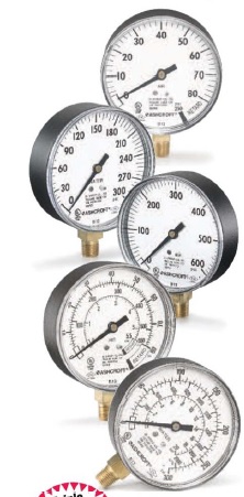
Ashcroft fire protection sprinkler gauges are Underwriters Laboratory listed and Factory Mutual approved for fire protection sprinkler service. The case material on Type 1005P, XUL gauges is ABS. The 0-300 psi pressure range is used on ‘wet” systems where water is available to the sprinkler heads. The 0-80 retard to 250 psi pressure range is used on dry systems where the lines are filled with air pressure until system activation. The 0-600 psi gauge is available for systems requiring higher pressures. Due to global demands for fire protection sprinkler gauges, Ashcroft offers UL listed, triple scale (bar, kPa, psi) dial gauges The patented PowerFlex movement with polyester segment is designed to provide unequalled shock and vibration resistance resulting in superior performance and extended gauge life. True Zero” indication, a standard feature on these gauges, reduces the potential rioli of installing a damagod gauge on your equipment.
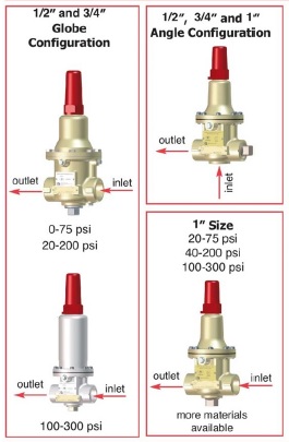
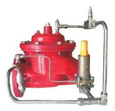
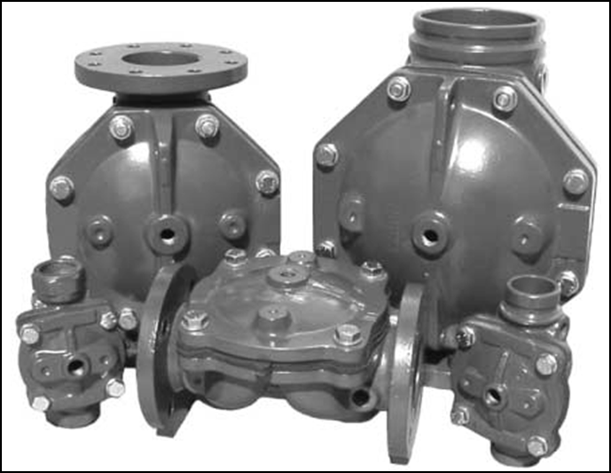
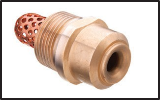
The Cla-Val Model 55L-60 (UL Listed, FM Approved) Pressure Relief Valve is a direct-acting, spring loaded, diaphragm type relief valve. The valve may be installed in any position and will open and close within very close pressure limits. The bottom plug may be removed and installed in the inlet to convertit to an angle pattern flow path.
• Available sizes 1/2″, 3/4″ and 1″
Size 1/2″, 3/4″ and 1″ Threaded NPT Temperature Range Water, Air: to 180°F Max
Materials
Body & Cover: Cast Bronze UNS C87850 – Standard Stainless Steel ASTM A743-CF-16F Monel Trim: Super Duplex Stainless Steel 303 Stainless Steel Monel
Rubber: Buna-N’ Synthetic Rubber Pressure Ratings Cast Bronze 400 psi Max. Stainless Steel 400 psi Max.
Other Materials Available on special order
Adjustment Ranges UL Listed 10 lu 75 psi. 20 lu 200 psi – 100 lu 300 psi Adjustment Ranges FM Approved 0 to 75 psi. 20 to 200 psi. 100 to 300 psi
*Pressure rating for water application. In accordance with the European Pressure Equipment Directive 97/23/EC, actual pressure rating is dependent upon fluid type and nominal pipe size.
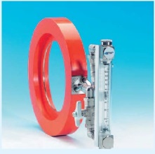
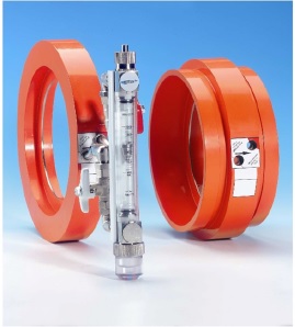
• High flows
•Direct reading Gases and liquids
•Between flange connections Compact construction
•Vertical or horizontal mounting
Gas Range – 20 – 7000 m2/h (air equiv)
Liquid Range – 2 – 1000 mo/n (water equiv)
Scale Length – 100 mm
Accuracy – +2% FSD
Temperature – -15 to 90°C
Pressure * – 20 bar max. (non shock)
Connections Flange wafer, bolted between flanges (DIN or BS10 Table E or D) Seals – Viton and polyurethane
Flow Tube Borosilicate glass
Float
Ashcroft fire protection sprinkler gauges are Underwriters Laboratory listed and Factory Mutual approved for fire protection sprinkler service. The case material on Type 1005P, XUL gauges is ABS. The 0-300 psi pressure range is used on ‘wet” systems where water is available to the sprinkler heads. The 0-80 retard to 250 psi pressure range is used on dry systems where the lines are filled with air pressure until system activation. The 0-600 psi gauge is available for systems requiring higher pressures. Due to global demands for fire protection sprinkler gauges, Ashcroft offers UL listed, triple scale (bar, kPa, psi) dial gauges The patented PowerFlex movement with polyester segment is designed to provide unequalled shock and vibration resistance resulting in superior performance and extended gauge life. True Zero” indication, a standard feature on these gauges, reduces the potential rioli of installing a damagod gauge on your equipment.
• Underwriters Laboratory listed and Factory Mutual approved – Corrosion-resistant ABS case
• Underwriters Laboratory listed and Factory Mutual approved – Corrosion-resistant ABS case
Ashcroft
•Flange or groove style connection.
•Horizontal or vertical pipes.
•Scaled in USGPM and dm/min
•Flow element: Polyester coated carbon steel body.
•Highly stable indicator readings.
•S.W.P: 20 barg
•Accuracy: + 2% of test range max.
– Relief valve: Limilsinlet pressure by relieving excess pressure
– Install the valve with adequate space above and around the valve to facilitate servicing. Refer to the Dimensions Table -Valve should be installed with the bonnet.cover) at the top particularity 8″ (DN200) and larger valve and any valve with limit switch Shut
The normally closed, spring-loaded pilot, sensing upstream pressure, responds to changes in pressure upstream of the main valve, and causes the main valve to do the same.
The net result is a constant modulating action of the pilot and main valve to hold the upstream pressure constant
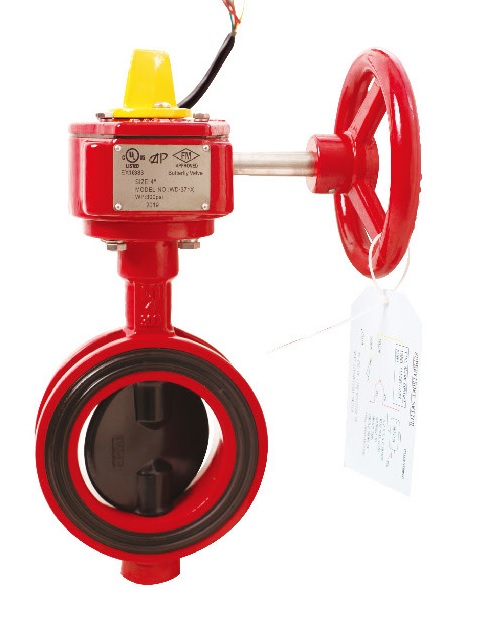
1. Maximum Working Pressure:300PSI(Max. Test Pressure:600PSI)
1. Maximum Working Pressure:300PSI(Max. Test Pressure:600PSI)
1. Maximum Working Pressure:300PSI(Max. Test Pressure:600PSI)
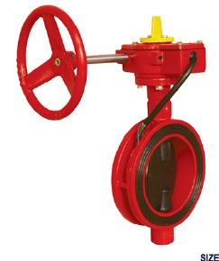
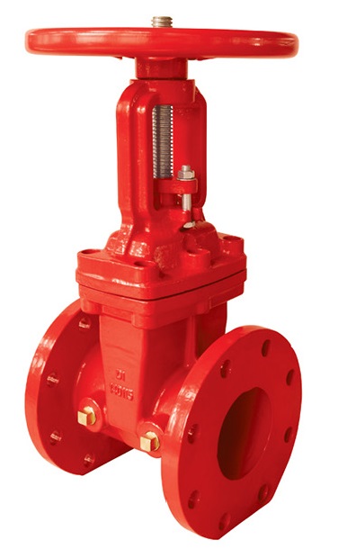
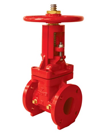
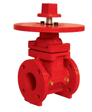
1. Design Standard:AWWA C515
1.Design Standard:AWWA C515
2.Nominal Pressure:300PSI
1.Design Standard:AWWA C515
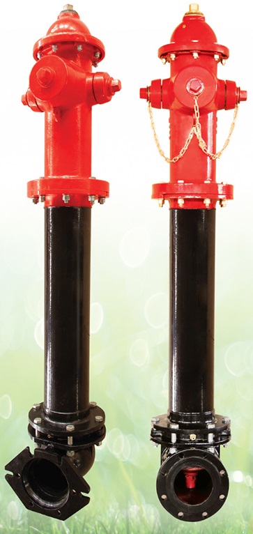
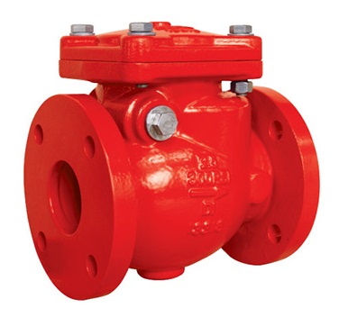
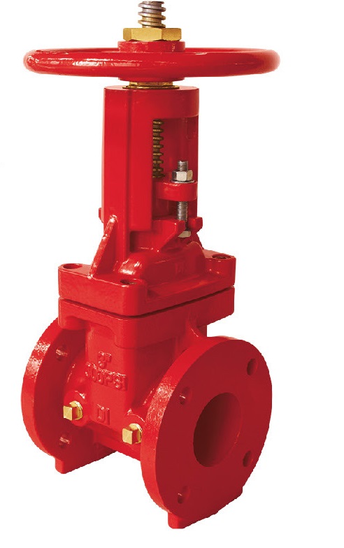
1.Design Standard:AWWA C508
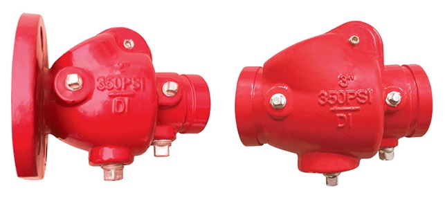
1.Installed in both Horizontal or Vertical Line with Upward Flow
1. Flange end 1-1/2 & 2 Inch (DN40 & DN50) DV-5 Valves are not offered.
• Flange Standard: ANSI 125 / 150, DIN2501 PN10/16 .
Nominal Pressure: 300PSI
– Nominal Pressure: 300PSI –
The TYCO Type HV Nozzles are open (non-automatic) directional spray nozzles with individual inlet strainers. They are designed for use in water spray fixed systems for fire protection applications where a high velocity water application may be required, such as for the protection of flammable liquids.
The Type HV Nozzles feature an integral strainer for use when the authority having jurisdiction (other than NFPA applications) requires the use of individual strainers in addition to main pipeline strainers for nozzles having an orifice diameter of 3/16 inch (4,8 mm) or less.
Available in brass or stainless steel, the six patterns of the Type HV Nozzles provide a wide variety of orifice sizes and distribution characteristics. As water passes through the internal swirl plate, a swirling action is produced, prior to the water being discharged through the orifice tip of the body, resulting in a solid conical spray pattern of water droplets being discharged over a defined area.
High velocity type nozzles are principally used in water spray systems for the protection of fixed hazards such as transformers, circuit breakers, diesel engines and diesel storage tanks, turbo alternators, lube oil systems, oil fire boilers, and similar hazards. They are capable of rapidly extinguishing oil fires by emulsification, cooling, and smothering. The surface cooling effects of high velocity type nozzles also minimizes the possibility of reignition after a fire extinguishment.
It is recommended that the end user be consulted with respect to the suitability of the materials of construction for any given corrosive environment. Effects of ambient temperature, concentration of chemicals, and gas/chemical velocity should be considered, at a minimum, along with the corrosive nature to which the nozzles may be exposed.
The TYCO Type HV Nozzles are a
TYCO Type HV Nozzles must be installed in accordance with this section.
General Instructions
A leak tight 1 inch NPT nozzle joint should be obtained by applying a minimum to maximum torque of 20 to 30 ft.-lbs. (26,8 to 40,2 Nm). A leak tight 1-1/4 inch NPT nozzle joint shgould be obtained by applying a minimum to maximum torque of 30 to 40 ft.-lbs. (40,2 to 53,6 Nm). Higher levels of torque may distort the nozzle inlet and cause impairment of the nozzle.
1. With pipe thread sealant applied to the pipe threads, hand tighten the nozzle into the nozzle fitting.
2. Tighten the nozzle into the nozzle fitting using an adjustable crescent wrench. With reference to Figure 1 the adjustable crescent wrench is to be applied to the wrench hex.
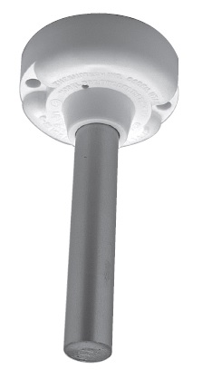
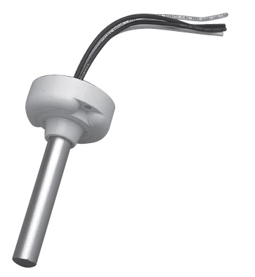
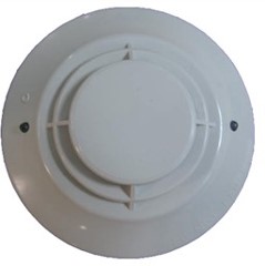
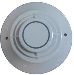
For interior mounting in any atmosphere that is compatible with terminal screw type connections.
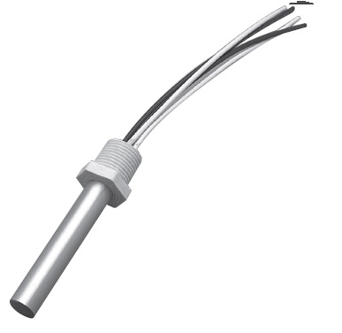
Hermetically sealed for moisture proof or dust proof installations. Requires no special back box. Has plastic hexagonal grip bushing with 1/2” conduit threads for attachment to threaded hub cover, or any outlet box. Must be hand tightened only. For indoor and outdoor use. Protect from direct sunlight and adverse weather conditions.
Hermetically sealed for moisture proof or dust proof installations. Requires no special back box. For indoor and outdoor use. Protect from direct sunlight and adverse weather conditions.
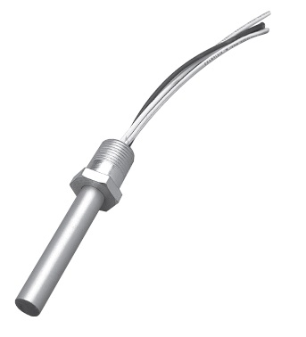
Explosion proof for installation in hazardous locations. Has hexagonal grip bushing with 1/2’ conduit threads for attachment to threaded hub cover of series JL fixture fitting as manufactured by Killark Electric Co., or equal. Must be hand tightened only. For Interior use.
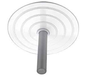
Decorative white plastic adapter plate for mounting 302, 302-AW and 302-ET detectors only.
The TYCO Type HV Nozzles are open (non-automatic) directional spray nozzles with individual inlet strainers. They are designed for use in water spray fixed systems for fire protection applications where a high velocity water application may be required, such as for the protection of flammable liquids.
The Type HV Nozzles feature an integral strainer for use when the authority having jurisdiction (other than NFPA applications) requires the use of individual strainers in addition to main pipeline strainers for nozzles having an orifice diameter of 3/16 inch (4,8 mm) or less.
Available in brass or stainless steel, the six patterns of the Type HV Nozzles provide a wide variety of orifice sizes and distribution characteristics. As water passes through the internal swirl plate, a swirling action is produced, prior to the water being discharged through the orifice tip of the body, resulting in a solid conical spray pattern of water droplets being discharged over a defined area.
High velocity type nozzles are principally used in water spray systems for the protection of fixed hazards such as transformers, circuit breakers, diesel engines and diesel storage tanks, turbo alternators, lube oil systems, oil fire boilers, and similar hazards. They are capable of rapidly extinguishing oil fires by emulsification, cooling, and smothering. The surface cooling effects of high velocity type nozzles also minimizes the possibility of reignition after a fire extinguishment.
It is recommended that the end user be consulted with respect to the suitability of the materials of construction for any given corrosive environment. Effects of ambient temperature, concentration of chemicals, and gas/chemical velocity should be considered, at a minimum, along with the corrosive nature to which the nozzles may be exposed.
The TYCO Type HV Nozzles are a
TYCO Type HV Nozzles must be installed in accordance with this section. General Instructions
A leak tight 1 inch NPT nozzle joint should be obtained by applying a minimum to maximum torque of 20 to 30 ft.-lbs. (26,8 to 40,2 Nm). A leak tight 1-1/4 inch NPT nozzle joint shgould be obtained by applying a minimum to maximum torque of 30 to 40 ft.-lbs. (40,2 to 53,6 Nm). Higher levels of torque may distort the nozzle inlet and cause impairment of the nozzle.
1. With pipe thread sealant applied to the pipe threads, hand tighten the nozzle into the nozzle fitting.
2. Tighten the nozzle into the nozzle fitting using an adjustable crescent wrench. With reference to Figure 1 the adjustable crescent wrench is to
be applied to the wrench hex.
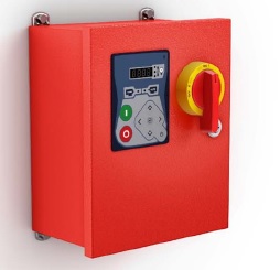
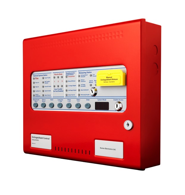
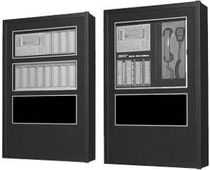
Sigma A-XT releasing panel offers outstanding value and performance for all
small to medium fixed fire-fighting installations.
With three initiating circuits as standard, release can be configured to
activate from any combination of detection zone inputs to allow (among
other combinations) any two from three types of activations for detection in
ceiling void, room and floor void applications.
The extensive configuration options of the Sigma A-XT allow the functionality
of the system to be extensively modified. The panel contains a large LED
display to enable easy configuration and control which also displays the time
remaining until release for added user safety.
The countdown time is duplicated on up to seven remote status units to
provide local indication of the system status.
With all the electronics mounted on a single, easily removable, steel plate
Sigma A-XT panels are both robust and easy to install. Sigma A-XT is supplied
in an enclosure that matches the design and colour of the Elite RS range and
is available in standard red or optional grey.
– UL864 and FM Listed
– Three initiation circuits as standard
– Any single zone or any combinations of zones can be
– configured to release
– Configurable first stage NAC delays
– Configurable detection delays
– Zero time delay upon manual release option
– Supports up to seven, four wire status indicators
– Built in Extract Fan control- Compatible with I.S. barriers
– Non-latching zone input option to receive signals from
other systems such as aspirating equipment
– Configurable releasing delays up to 60 seconds in 5
second stops
– Configurable releasing duration up to 5 minutes in 5
second steps.
– Countdown timer shows time remaining until
release
Construction : 1.2mm mild sheet steel
IP rating: IP30
Finish: Epoxy powder coated
Colour- lid & box: Red RAL 3002 (optional grey BS 00 A 05 semi-matt)
Mains supply: 230V AC or 115V AC
Mains supply fuse: 1.6Amp (FL.6A L250V)
Power supply rating: 3 Amps total including battery charge 28V +/- 2V
Maximum ripple current: 200 millivolts
Battery Type (Yuasa NP): Two 12 Volt 7Ah sealed lead acid in series
Battery charge voltage: 27.6VDC nominal (temperature compensated)
Battery charge current: 0.7A maximum
Battery fuse: 20mm, 3.15A glass
Maximum current: draw from batteries 3 amps
Quiescent current of panel in mains fail: 0.095A
R0V output: Fused at 500mA with electronic fuse
Sounder outputs: 24V Fused at 500mA with electronic fuse
Fault relay contact rating: 30VDC 1A Amp maximum
Fire relay contact rating: 30VDC 1A Amp maximum
Local fire relay contact rating: 30VDC 1A Amp maximum
First stage contact rating: 30VDC 1A Amp maximum
Second stage contact rating: 30VDC 1A Amp maximum
Extract contact rating: 30VDC 1A Amp maximum
Zone quiescent current: 2mA maximum
Terminal capacity: 12 AWG
Number of detectors per zone: Dependent on type (maximum 32)
NAC rating: 0.5A per circuit
Detection circuit end of line: 6K8 5% 1/2 Watt resistor
Monitored input end of line: 6K8 5% 1/2 Watt resistor
Sounder circuit end of line: 10K 5% 1/4 Watt resistor
Extinguishant output: EOL 1N4004 Diode
No. of initiating circuits: 3
No. of NAC circuits: 2 x 1st stage, 1 x 2nd stage
Extinguishant release output: Fused at 1 Amp
Extinguishant release delay: Adjustable 0 to 60 seconds (in 5 second steps)
Extinguishant release duration: Adjustable 60 to 300 seconds (in 5 second steps)
SIL, AL, FLT, RST inputs: Switched -ve, max resistance 100 ohms
Zone normal threshold: 8K ohms to 1k ohm
Detector alarm threshold: 999 ohms to 400 ohms
Call point alarm threshold: 399 ohms to 100 ohms
Short circuit threshold: 99 ohms to 0 ohms
Monitored inputs normal threshold: 8K ohms to 1k ohm
Monitored inputs alarm threshold: 999 ohms to 100 ohms
Monitored inputs short circuit threshold: 99 ohms to 0 ohms
Status unit/ Ancillary board connection: Two wire RS485 connection
Status unit power output: Fused at 500mA with electronic fuse
Access Level 2 Access Level 3
Test Zones 1 to 3 Sounder delay
Disable Zones 1 to 3 Coincidence detection
Disable 1st stage alarms Disable panel features
Disable pre-activated 1st stage relay Zone alarm delays (detectors)
Disable pre-activated 2nd stage replay Zone alarm delay (call stations)
Disable extract fan output Configure Zone for I.S barrier use
Disable manual release input Zone short circuit alarm
Disable releasing sub system Zone non latching
Activate extract fan output Zone inputs delay
Activate alarm delays Extinguishant release time delay
Extinguishant release duration timer
Extinguishant reset delay timer
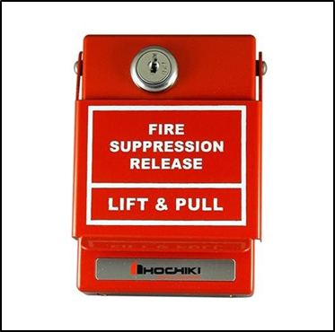
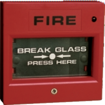
HPS-DAK-SR is a dual action (lift & pull) fire suppression release manual pull station. HPS-DAK-SR model is constructed of a solid die cast housing and comes in glossy red. The back switch plate is plated steel. The electrical switch is rated for 10 Amps @ 120 VAC normally open contact rating. All models are connected via terminal block connections.
– Metal Construction
– Enclosed switch with glass rod (included)
– UL, CSFM Listed
– Made in USA
Model: HPS-DAK-SR
Contact: (1) Form A
Contact Rating: 10A @ 120 VAC
Operating Temperature: -30°F (-35 °C) ~ 150°F (66°C)
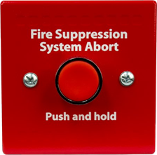
The K1823-x0 is a single action push button abort switch. The K1823-x0 is compatible with the Sigma A-XT fire alarm control panel and connects via terminal block connections.
– UL Listed and FM Approved
– Capable of aborting releasing operation
– Available in red or gray
– Includes a back box for surface mount
Model: K182310 (red)
K182340 (gray)
Switch Rating: 1A @ 30VDC
Dimensions: 3.81” W x 3.81” H x 2.32” D
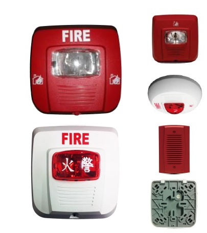
The System Sensor line of notification devices offers the most
flexibile and easy-to-use line of horns, strobes, and horn strobes in
the industry. With white and red housing, universal fire symbol and
a ceiling mount accessory available these devices can meet virtually
any application. They also mount to a wide variety of back box sizes
to offer the most flexibility in installation.
This line of devices features a wide variety of features that
simplifies installations. The mounting plate allows the devices to
be compatible with a wide range of back box sizes. Settings for the
strobe and horn are done using easy to set rotary switches on the
back of the device. Synchronization is achieved without the use of
additional modules; when powered with a filtered DC source, the
strobe portion is capable of self synchronization for 30 minutes per
NFPA 72.
Three candela options are available for the strobe when it works on
24 volts or full wave rectified power. Only 15 candela is available
for strobe when it works on 12 volts. On the horn strobe model, high
and low volume are options for the horn as well as a continuous tone
or temporal 3 output. The mini horn model has a continuous tone
output and one volume setting.
Available accessories include a round trim ring to adapt the wall
device for ceiling mount applications. Simply install the round ring
over the square device for a perfect fit on the ceiling. An adapter
plate is also available for the mini horn. It fits to a wider range of
back boxes and fits with the family look of the horn strobe and
strobe devices.
– Mounting plate included for compatibility with a wide range of
back box sizes
– Three field selectable candela settings: 15, 75, and 115
– Easy to use rotary dials for selection of candela and horn settings
– Built in synchronization feature keeps strobes in sync for
up to 30 minutes
– Strobes Listed to UL 1638; Horns Listed to UL 464
– Horn settings on the horn strobe model include high and low
volume, continuous or temporal 3 tone
– Round trim ring available for ceiling mount applications
– Universal Fire symbol is language independent
– Trim plate allows mini horn to mount to a variety of back boxes
and fit aesthetically with the horn strobe and strobe
Standard Operating Temperature: 32℉ to 120 ℉ (0℃ to 49℃)
Humidity Range: 10 to 93% non-condensing
Strobe Flash Rate: 1 flash per second
Nominal Voltage: Regulated 24 DC/FWR1 or regulated 12 DC/FWR#
Operating Voltage Range: 16 to 33 V (24 V nominal); 8 to 17.5 V (12 V nominal)
Input Terminal Wire Gauge: 14 to 18 AWG*
Strobe And Horn Strobes Dimensions(including lens): 5.15″ L × 5.0″ W × 1.5″ D (131 mm L× 127mm W × 38mm D)
Ceiling Trim ring Dimensions (sold as a pack of 5): 6.8 ” dia / 1.5″ depth (173 mm dia / 38mm depth)
Mini Horn Dimensions: 4.6″L × 2.9″ W × 0.45″ D (117 mm L× 74 mm W× 11.5mm D)
Mini Horn Trim Plate (sold as a pack of 5): 5.1″ L × 5.0″ W × 1.73″ D (131 mm L × 127 mm W × 43 mm D)
# Full Wave Rectified (FWR) voltage is a non-regulated, time-varying power source that is used on some power supply and panel outputs.
* Mini horn is rated for 12 to 18 AWG
The NFS2-3030 is an intelligent Fire Alarm Control Panel (FACP) designed for medium- to large-scale facilities. Fire emergency detection and evacuation are extremely critical to life safety, and the NFS2-3030 is ideally suited for these applications. The NFS2-3030 is part of the ONYX® Series of products from NOTIFIER. The NFS2-3030 is ideal for virtually any application because it features a modular design that is configured per project requirements. With one to ten Signaling Line Circuits (SLCs), the NFS2-3030 supports up to 3,180 intelligent addressable devices.
Information is critical to fire evacuation personnel, and the NFS2-3030’s large 640-character Liquid Crystal Display (LCD) presents vital information to operators concerning a fire situation, fire progression, and evacuation details.
A host of other options are available, including single- or multi- channel voice; firefighter’s telephone; LED, LCD, or PC-based graphic annunciators; networking; advanced detection products for challenging environments, and many additional options.
– B224BI(A): 6.2″ (15.748 cm) diameter.
Shipping weight: 4.8 oz. (137 g).
JTW-BD-FST-851C:–20°C to 38°C (–4°F to 100°F).
center. FM approved for 25 x 25 ft. (7.62 x 7.62 m) spacing.
Relative humidity: 10% – 93% noncondensing.
The 500KC Callpoint is designed to be used as a component of a compatible fire control system using System Sensor analogue devices. It is a dedicated addressable callpoint for installation on the two wire communication circuit providing both signal of alarm to the monitoring control panel and local LED indication of activation.
The M500K can connect up to 8 conventional callpoints from terminal 3(-), 4(+), as shown Fig.1. Any of the interfaced conventional callpoint can send alarm signal to the panel as well as the M500K if it is activated. On the last conventional
callpoint, a 10 k End-of-Line resistor must be connected for wiring supervision.
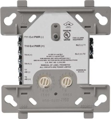
• Built-in type identification automatically identifies these devices to the control panel.
• Internal circuitry and relay powered directly by two-wire SLC loop. The FCM-1(A) module requires power (for horns, strobes, etc.), or audio (for speakers).
• Integral LED “blinks” green each time a communication is received from the control panel and turns on in steady red when activated.
• LED blink may be deselected globally (affects all devices).
• High noise immunity (EMF/RFI).
•The module may be used to switch 24-volt NAC power, audio (up to 70.7 Vrms).
• Wide viewing angle of LED.
• SEMS screws with clamping plates for wiring ease.
• Direct-dial entry of address 01– 159 for
Normal operating voltage: 15 to 32 VDC.
Maximum current draw: 6.5 mA (LED on).
Average operating current: 350 μA direct poll, 375 μA group poll with LED flashing, 485 μA Max. (LED flashing, NAC shorted.)
JSM-FMM-1C is a standard-sized module (typically mounts to a 4″
[10.16 cm] square box) that supervises either a Style D (Class
A) or Style B (Class B) circuit of dry-contact input devices.
JSM-FMM-101C is a miniature monitor module a mere 1.3″ (3.302 cm) H x 2.75″ (6.985 cm) W x 0.5″ (1.270 cm) D that supervises a Style B (Class B) circuit of dry-contact input devices. Its compact design allows the module to be mounted in a
• Built-in type identification automatically identifies these devices to the control panel.
• Internal circuitry and relay powered directly by two-wire SLC loop. The FCM-1(A) module requires power (for horns, strobes, etc.), or audio (for speakers).
• Integral LED “blinks” green each time a communication is received from the control panel and turns on in steady red when activated.
• LED blink may be deselected globally (affects all devices).
• High noise immunity (EMF/RFI).
•The module may be used to switch 24-volt NAC power, audio (up to 70.7 Vrms).
• Wide viewing angle of LED.
• SEMS screws with clamping plates for wiring ease.
• Direct-dial entry of address 01– 159 for
Normal operating voltage: 15 to 32 VDC.
Maximum current draw: 6.5 mA (LED on).
Average operating current: 350 μA direct poll, 375 μA group poll with LED flashing, 485 μA Max. (LED flashing, NAC shorted.)